Minimoog
After playing on many different synths and copying several designs. I decided that I had to have a minimoog...
Unfortunately the cost of a second hand minimoog is anything between £1000-£2000 depending on age and condition. So the only choice I have is to look at doing my own copy with the aim of keeping the circuits and design as original as possible.
Having never played one, or seen one until a few months ago I have managed to amass a reasonable collection of circuits and pictures in order to help me in my quest.
I have to thank the owner of fantasyjackpalance
http://www.fantasyjackpalance.com/fjp/sound/synth/synthdata/16-moog-minimoog.html
For a fantastic site full of minimoog information. The pics in particularly have been invaluable. I have been fortunate enough also to photograph and measure up an early model D.
After looking at the nightmare wiring and the amount of interconnects I have decided to layout the PCB's and attach the pots to the PCB. This changes the overall design as the circuits on each of the boards will now need re-arranging. I have chosen to do 6 PCB's with the following circuits.
Oscillator range/tune PCB, probably with octave buffers as well
VCO PCB - this will be the early transistor based circuit, but with the tempcos actually resting on the expo pair.
Noise/mixer/power supply PCB
Filter PCB
EG PCB
VCA/output PCB
Due to my previous attempts at clones and never been happy I have chosen to copy the circuits exactly with minimal exceptions, hopefully this will result in something that sounds as special as the original.
Feb 26th 2004
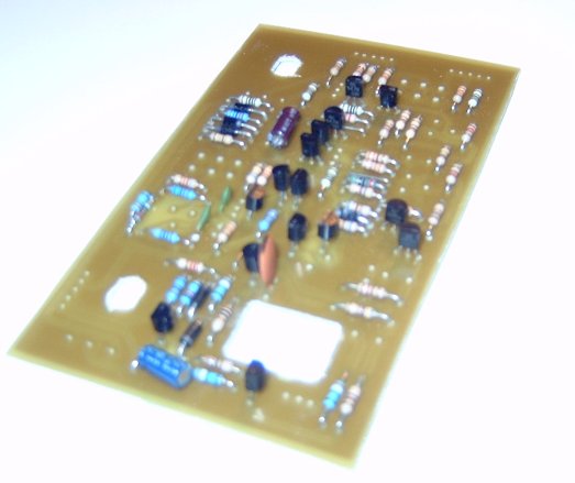
Filter PCB
The filter PCB is an identical copy of the circuit with the exception of adding a 3046 to save transistor matching. (CAD 2 is on it's way)
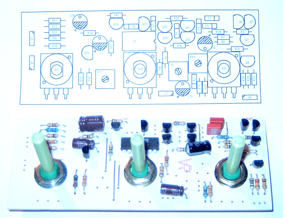
EG PCB
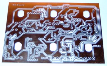
EG PCB contains original dual ADS contour generators
April 21st 2004
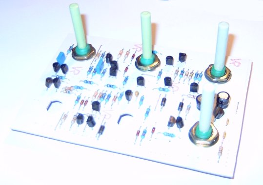
VCA Backend PCB
Backend PCB contains 440Hz reference generator, voltage controlled amp and headphone amp - hole is for headphone socket.
Mixer/Noise and Power supply PCB
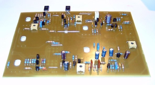
The mixer PCB contains all 5 mixer pots, switches, noise generator, modulation mix amplifier as well as the dual voltage regulator
May 12th 2004
Making it work
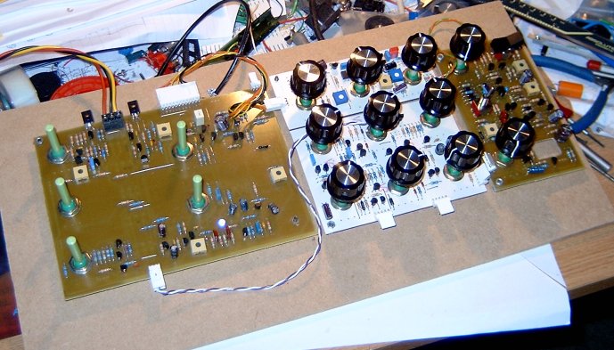
Above picture shows first 4 PCB's mostly wired and ready for testing.
First to be tested is the power supply - it draws 2A until Q19 fails. I managed to fit an NPN part instead of a PNP.
Noise generator works fine
Mixer works fine - although I have not yet got switches.
Filter board does not work and after lots of debugging I realise that the CA3046 that I used for the ladder must have pin 13 (substrate) connected to the lowest potential in the cct, and I used it at the top of the ladder.
A440 reference and main/headphone amps are running. (A440 is 50 Hz too slow, but I'm sure it can be trimmed out)
Dual EG and VCA are to be tested next.
Minimoog switches
These are probably the hardest component to find or substitute - especially if like me you want the same look and feel as the original. After going PCB mount on pots then the switches really had to be PCB mount. This made it practically impossible to get anything like the original, so I turned to making my own and looking into getting a soft tool made in order to replicate more.
I chose to use a C&K switch body as this is a DPDT rocker not too dissimilar to the original other than switch length.
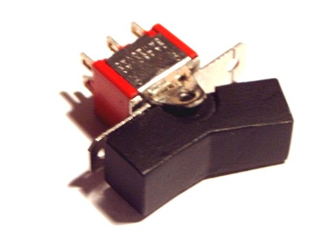
Pictured is the prototype which I will be getting a soft tool made from. Fingers crossed I can then get the switches moulded in the original three colour scheme.
June 2nd 2004
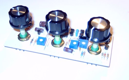
Part Assembled with front panel
Front panel placed over PCBs and knobs added to check knob spacing, I am also awaiting quotes for switch tooling - and hoping it meets my budget !
June 10th 2004
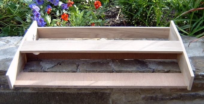
Cabinet construction
Cabinet pictured 90% complete, just requires front panel strip which I will fit after fitting a suitable donor keyboard mechanism.
July 16th 2004
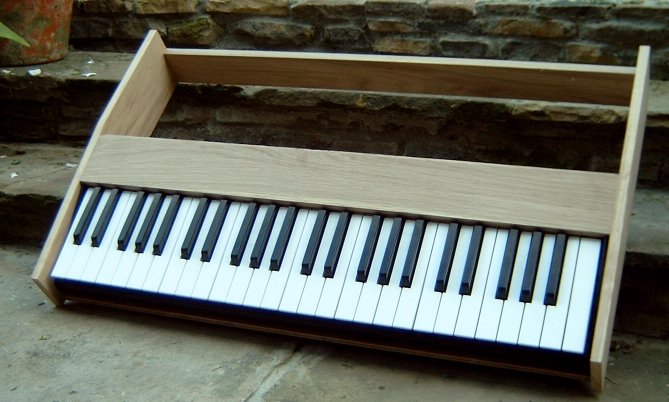
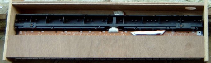
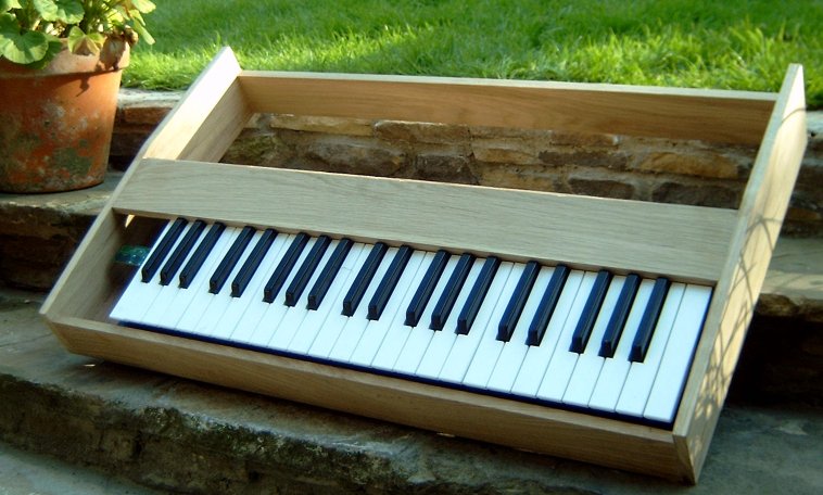
Adding the keyboard
Cabinet fitted with keyboard, donor was a Casio keyboard, once mountings are finished the first five keys need to be removed
as the original keyboard starts at F and is three and a half octaves, this will then create space for the controllers.
Front panel strip still to fit, CAD 2 of VCF complete, CA3046 now wired correctly.
July 23rd 2004
Mounting the keyboard
Keyboard now 3 1/2 octaves and mounted in cabinet, front strip also added.
More pictures of cabinet here
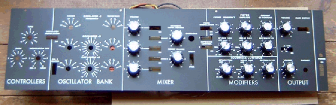
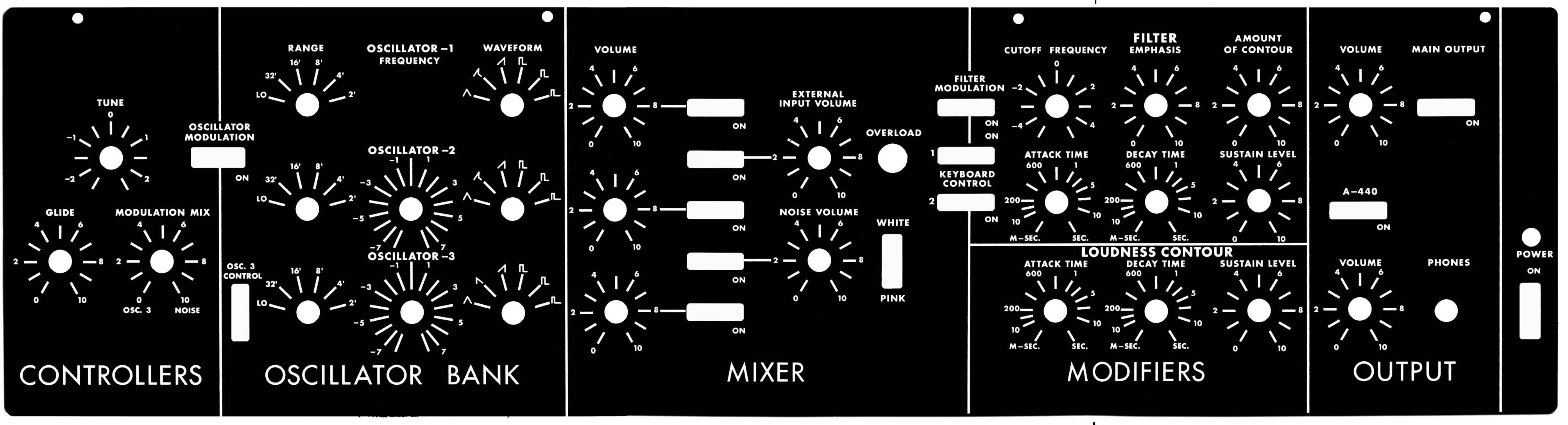
Front Panel Artwork
Schematics
Mixer / Power supply / Noise / Modulation mix
VCA / Headphone amp / A440 ref.
These are faithful reproductions of the originals - even reference designators, they are not my own and I do not accept any responsibility for any errors contained within. I am just happy to share my own copies which should save any other poor soul the trouble I have had decrypting the originals.
any comments/suggestions ( but not can I have your artworks... ) please contact me e-mail
Last updated 8th June 2009!!! (added VCO schem)